Leaderboard


Popular Content
Showing content with the highest reputation on 12/10/2014 in all areas
-
please dont have a go at me but i do like that black mk41 point
-
Phew! glad we don't have that feature on LS400s ,could be lethal to cyclists.1 point
-
The main software for Lexus-Toyota is Techstream, while if you need only to clear codes with a BT interface and a cell phone there is Torque or Dashcommand for general purpose and Carista for Lexus cars options.1 point
-
what's the Alfa's turning circle like though? :P Well imagine a main road that could fit 4 lanes of traffic across it,i could just about make the U turn from kerb to kerb :D1 point
-
You just can't do these kind of things to these cars, it just doesn't work. The only time it may work is when you see them in America and they've thrown thousands at them.1 point
-
I don't know if the transponder is different, within the engine ECU a transponder serial number either gets marked as a master or a valet. A key unknown to the vehicle is essentially neither a master or a valet, it is a foreign key. To alter any configuration (add or delete a key) you must first have a known master key for the programming functions to work. Not just any key, but a key registered as a master within the ECU database. One of the programming functions is to delete all keys and re-add the ones you have. This is a good thing to do, it means key that are not in your possession will no longer work.1 point
-
Most people do it the other way around with imported Harriers. They want to be seen in a Lexus rather than a Toyota as it is marketed as a higher luxury brand. It is like taking badges of an Audi A3 and replacing with VW Golf ones.1 point
-
Totally over my head.........sorry.1 point
-
I guess they put a lot of store on their Allard name, hence the valuation as a piece of history. Their problem is convincing somebody else, not helped, imo, by the car hitting every branch of the ugly tree on the way down.1 point
-
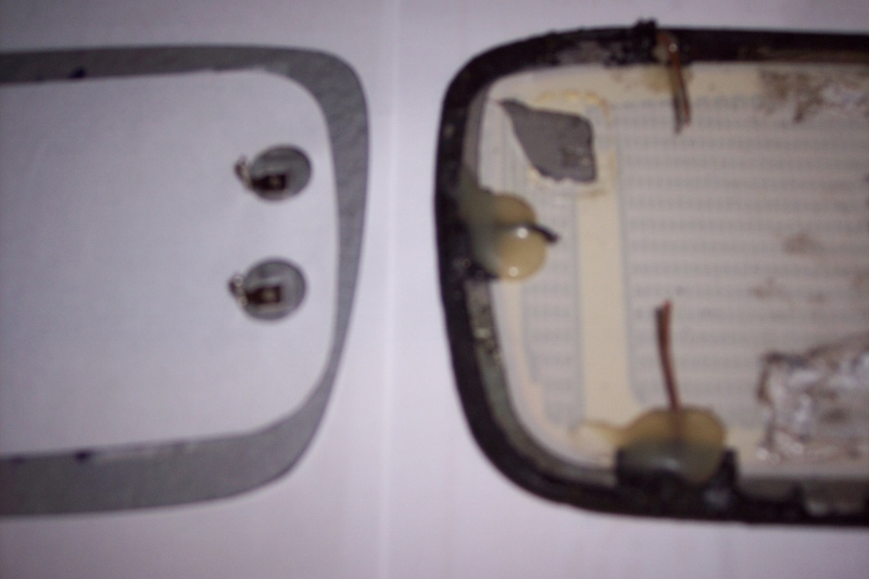
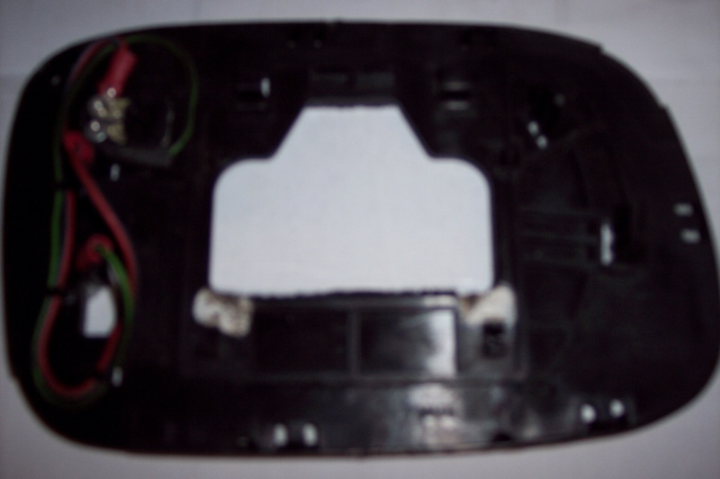
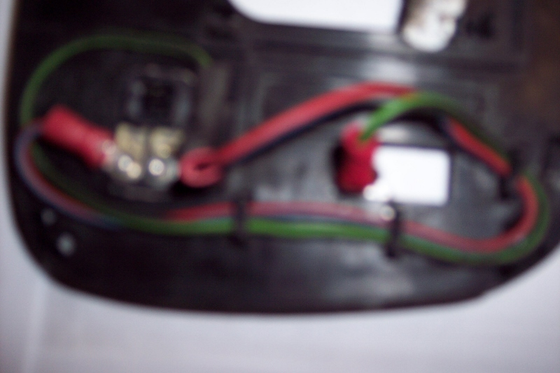
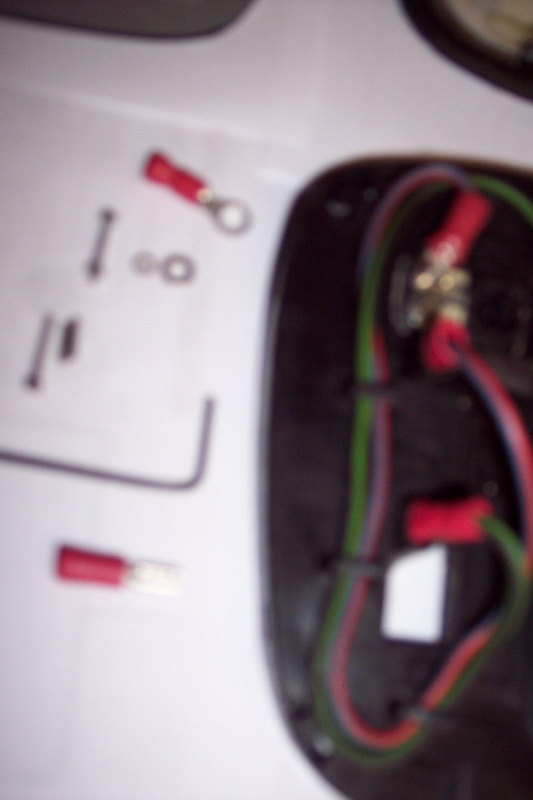
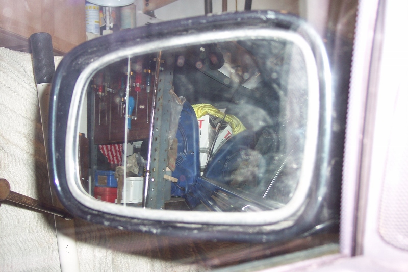
Paul, thanks for the link to the eBay mirrors. I have in fact already purchased two of these, passenger and driver side, and have just finished fitting the passenger one. I have set out below a description of how I went about doing this, with a few photos of what is involved, in case this is of interest to anyone else who might be thinking of fitting this non-original heated mirror. The Mirror Glass Purchased The mirror glass I bought was from Car Parts Market Ltd (eBay ID: car-parts-market) and the item was described as a Passenger Left Side Wide Angle Heated Wing Mirror Glass for Lexus LS400 95-00. The cost is £10.99 with free postage/packing. There was a Buy 1, Get 1 at 50% off, however, so I decided to buy a Drivers Right RHS mirror as well for the other side to be fitted if and when needed (at a total cost of £16.48 for the two). Removal of Existing Mirror Glass The existing mirror glass and its backing plate were removed by inserting the tip of a screwdriver between the bottom of the mirror (backing plate) and the mirror housing, in the middle about half way along, with a rag round the screwdriver tip to protect the mirror housing. Lever the screwdriver downwards to force the backing plate forward. This releases the two plastic clips on the backing plate from their location in the bottom of the (white) mirror electric adjustment plate. This is basically a push-fit method of retention but the clips do not release easily and a fair amount of pressure needs to be applied. Once released, the mirror can then be pivoted upwards from the bottom so that it is horizontal. This releases the two “J” clips holding the mirror backing plate to the top of the mirror electric adjustment plate and the mirror plate can then be pulled forward from the mirror housing. There is a small plug with two wires (black with red and black with green) around the top left hand corner of the backing plate and this is the heater plug. Pull it off the twin pins attached to the mirror glass (two pins close together). You will also see other wires - two brown and one blue – but leave these for the moment until you have separated the mirror glass from the backing plate. Separating the Existing Mirror Glass from the Backing Plate In order to separate them, the black plastic cover around the edge of the glass (the bit that looks white in Photo 5 – see below - showing the new mirror glass fitted...) needs to be removed. This is pushed on over the mirror glass from the front and there are several small rectangular slits in it (about 5 mm long and 1 mm wide) around the back edge of the cover. These fit into raised sections on the backing plate to hold the cover in place. The cover is removed by levering the edge of the cover up and forward at each of these sections using a small screwdriver. Once all are released the black plastic cover can be pulled off the front of the glass. The mirror glass will still be stuck onto the backing plate and will need to be gently levered off. The places where mine was stuck were centrally at the top and bottom edges of the mirror – a smaller strip at the top about 30mm x 7mm and a larger one at the bottom about 50mm x 20mm. The mirror could be easily separated from the white adhesive substance used to hold it in place. You can see the white adhesive on the old mirror glass in the Photo 1 at the extreme right hand edge of the picture. You can also see in Photo 1 two brown wires and one blue one attached to the glass. My guess is that this wiring is for the mirror’s auto-dimming function. As my replacement mirror has no auto-dimming, these wires were not needed so they were cut off and taped up. I did remove the clear silicon covering the wire to mirror glass join on the brown wire on the top edge of the mirror to see if the wire could be pulled off at the connection but it could not. It looked like a small spade connector was used but with a dab of solder on it to prevent it coming apart. So the wires were cut instead. The wires have been pushed into a wiring sleeve and placed at the back of the mirror housing so they can still be used in future if someone wants to fit an OE mirror glass. Removing the Twin Pin Connector from the Existing Mirror Glass The mirror on the left hand side of Photo 1 is the new mirror glass (it’s actually the drivers’ side glass not the passenger side, as I had already fitted the passenger side glass when I took this photo). You can see that the new glass has two separate connection terminals for the heated element which are some distance apart, whereas the original has twin pins close together onto which the small two wire plug is fitted (as indicated above). I decided to use the wire plug and twin pin connector attached to the original mirror glass if possible (it was) and make up connecting wires between the twin pin connector and the terminals on the new mirror glass. Below each of the twin pins is a metal connector. This has a thin layer of white silicon covering it and if you scrape this away you will see the metal connector underneath it. The other side of the connector is attached to the glass. You can see what the connector looks like by looking at the top right hand corner of the mirror glass in the photo I posted up when starting this thread in September. Each connector is a piece of metal with what look like two pin heads in it, one above the other. The pin connectors can be levered apart from the glass, but they don’t part company easily and care needs to be taken so that they remain intact. I found using a small screwdriver to be the most effective means of forcing them apart. In the photo of the (new and) old mirror glass, the grey section in the top left hand corner of the old mirror glass shows from where the connectors were removed. They were at the bottom of the grey section. By chance, the section removed extended upwards to include a plastic ‘flap’ of material as well. Try to do this if you can, as it proved useful later. I put this on one side till I had done the next job of making the new mirror glass fit on the backing plate. Positioning the New Mirror Glass on the Backing Plate To correctly position the new mirror glass on the backing plate, cut outs in the plastic backing plate need to be made so that the two separate connection terminals protrude through and the glass fits flush with the backing plate. The terminals are quite close to existing cut outs (the top one is for the heating wire plug) and I found it easiest to extend these cut outs so that the terminals went through. I used a small coarse square file to extend the cut out in the direction needed e.g. extending the top cut out downwards. Once this has been done, the twin pin connectors removed from the old mirror glass can be turned 90 degrees to the right from their normal position and can be trial fitted into the top cut out. Insert the ‘flap’ of material behind the backing plate on the right hand side of the cut out and the other end of the connectors can then be pressed inside the left hand side of the cut out. I found that this made a flush fit which held the connectors firmly in place. I removed the connector when satisfied with the fit. With the glass correctly positioned and flush with the backing plate, I did a trial fit of the black plastic cover around the edge of the glass. Then I marked the position on the big (white) area of the back of the mirror that is visible through the backing plate – see Photo 2 - so I knew where it needed positioning to stick it in place. To stick mine, I removed most of the white sticky substance and replaced it with another similar strip that I had. In the position where these stick to the new mirror glass, I removed the covering paper from the new mirror to reveal the adhesive strip underneath (belt and braces approach ...). I decided against removing all the covering paper, which extended over most of the mirror, as much of the adhesive would not be in contact with anything. I pushed the mirror glass onto the backing plate, making sure it was correctly positioned, and pressed firmly on the sections where the adhesive was. I then put the black plastic cover over the front of the mirror glass and pressed the rectangular slits into the raised sections of the backing plate to hold it in place (see above). Wiring the Twin Pin Connector to the New Mirror Glass Terminals The two separate terminals on the new mirror glass each needed to have a wire attached to them, with one wire going to one of the twin connectors and the other wire going to the other connector. I did not have any wiring that was the same colour as the wiring on the small plug (black with red and black with green) so I used the nearest I had which was red with blue and green with black. The wire was connected to the terminals on the new mirror glass using a (female) 2.8mm spade connector used for radio speakers etc. This was crimped onto the end of the wire and the connector opened up a little using a small screwdriver inserted into the connector end, as the (male) connector on the mirror glass was too thick for it to fit on without doing this. I crimped a small ring connector onto the other end of the wire. The plan was to connect these wires to the twin connectors by drilling a small hole through the centre of the lower pin head on each of the two connectors (i.e. the pin head furthest away from where the wire plug pushes into the twin pins) and then using a micro nut and bolt to fasten the ring connector. I used a very small drill (starting with a 0.5mm one) to drill a hole and increased the size of the hole to 2mm. I sourced some micro nuts and bolts locally at an engineers’ merchant, EC Pitchers in Walsall (they have a website: www.ecpitcher.co.uk). The only 1.5mm thick bolts they had were about twice as long (13mm) as I needed but I was able to cut them down with a small hacksaw after fitting them. They had an allen key head and the width of the bolt head was 3mm, which meant I needed to use a couple of small washers to prevent the bolt head going through the ring connector, and the nut fitted OK on the other side of the 2mm hole as it was 3.1mm wide. Photo 3 (a bit blurred) shows the wires connected up. The red plastic sleeve on the green wire ring connector was removed and replaced with a thin black sleeve because of restricted access for the green wire. Photo 4 shows a second view of the connections with the materials used on the left of the photo – from top, a small ring connector; a micro bolt with nut screwed on the end and to the right the two small washers used to prevent the bolt head going through the ring connector; a micro bolt without a nut and to the right the two sections of bolt cut off after fitting (this looks like one thicker piece but is the two sections next to each other); the allen key for tightening the bolt; and a (female) spade connector. You will see on both Photos 3 and 4 that the lower spade connector has been bent so that it projects inwards to the centre of the backing plate. The connector was removed from the mirror terminal to bend it and then refitted. The reason it was bent is that, when the backing plate is fitted onto its mountings in the mirror housing, there is a section of metal in the housing which is in the way. Without being bent, the connector may be damaged when re-attaching the backing plate in the housing and/or the section of metal may prevent the mirror being attached properly. Refitting the New Mirror Glass and Backing Plate I connected the small two pin heater plug to the twin pins, held the mirror horizontally to insert the “J” clips, lowered the bottom of the mirror down and then firmly pushed it into place. The mirror glass as fitted is shown in Photo 5. The job took some time to do and was quite fiddly but, provided the heater element works, it will have been worth the effort. Even if it doesn’t, at least I now have a mirror through which I can see properly!!
 1 point
 -
I imagine they buy German instead.1 point
-
Why would you want to do this?1 point