Leaderboard

Popular Content
Showing content with the highest reputation on 06/11/2014 in all areas
-
You do know its a 'stuffed' Meerkat and not a real one I hope2 points
-
Hi Guys, Following lots of interest in the leather key fobs Stu, Roheel, I and others have for our cars, I'm pleased to tell you that Paul over at Whifbitz can get these for you. The fobs can be found here on their website: http://www.garagewhifbitz.co.uk/lexus/is-f/lexus-is-f-keyfob.html Cost is £84 each including VAT, import duties etc. Please understand these can only be sourced from Japan, hence the price. Let me know if anyone has any questions. Cheers. Peter :)1 point
-
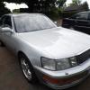
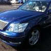
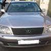
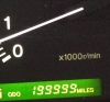
Bit of a light hearted discussion however someone seemed to think that it is FACT that the LS430 is a better car so I just wanted to put my side of the argument in a non argumentative way :P My LS400 is brilliant because..........................................: It has TWO HUNDRED AND SIXTY TWO THOUSAND MILES on the clock and it still drives like its brand new !!! My air conditioning blows out of the vents at MINUS 1.5°C The air suspension has never broken down and left me "carless" (because it doesn't have it) The rear fridge hasn't failed and needed capping (because it doesn't have one) I have the 1UZFE engine which does not suffer from Valve Seat Recession on LPG (I believe the 3UZFE does) The battery on my LS400 does not go flat if I leave it for a while (does not have passive keyless entry) My exhaust being FULLY stainless (apart from the Y-piece) is still in perfect condition, I wonder how the economy exhaust is on the LS430 being mild steel ?? The LS400 comes with standard 16" wheels whereas the LS430 comes with 17" meaning more expensive tyres for the LS430 The LS430 has too many toys to go wrong in my opinion Anyway feel free to fight your corner I challenge ye to a duel !!!!1 point
-
Here's a pic of Rudy's ECU, with:- 100uF 10v (2) 47uF 63v 220uF 16v 15uF 35v (2) not as advertised! 47uF 63v not as advertised! 10uF 50v (2) The American thread did say that sometimes there are differences. The board is difficult, access is ok as the board isn't too densely populated, but the plated through holes are the very devil to desolder and clear. I ended up cutting the old caps off and pushing the remaining leads through to the back, then clearing the holes with a solder sucker, which I really don't like using as you have to watch for bits of solder splashing about. I had the iron up at a much higher temperature than I would normally use and it took a while for the heat to melt the solder right through the board. No sign of leaking or swelling, Rudy has the old caps if anyone has the equipment and cares to do any measuring. I measured the voltage at the temperature sensor socket with a 2k resistor across it, can't really explain the before readings, a 1.5 volt ripple is ridiculous, could be my error, went down to 40mv afterwards.1 point
-
Oh dear then, .................. I have 6 capacitors in my replacement kit !!! Malc1 point
-
Because they joined the euro ;)1 point
-
Here's some pics - first, that LFA: All-electric Tesla - 300 mile range (yeah, right): ...but it looks great and check out the dash - all touchscreen, no buttons at all: Jaguar XF estate - best looking estate ever? BMW i8: My personal favourite - Aston Martin Vanquish convertible: Second favourite - Maserati Quattroporte:1 point
-
I was just about to ask the same question! I've been doing a bit of research on this recently, as I want to raise the lights a smidgen to increase the range - the main beam hits the road too close to the car, so you feel you're driving into a black hole at speed on a dark night. This despite the fact that dealer and MoT station insist that the lights are correctly adjusted. There was a thread on here a few years ago, but replies were links to workshop manual pages and now seem to be broken. I've got the workshop manual - and the instructions are here: http://tinyurl.com/nfwmc82 This says to get to the corner of the wing where it meets the headlight (having removed the front and side covers and the 'fender protective cover - the strip at the side of the top of the wing) and turn the adjustment screw - one for horizontal and one for vertical. The illustration seems to show a cross head driver and another version of the workshop manual (which claims to cover both IS250 and IS200) shows and specifies a phillips head driver. However, when you get there, there is absolutely no sign of any adjustment screws or anything you can turn with a screwdriver. See the following pictures (some of which I have lightened somewhat to try and show the dark recesses) http://tinyurl.com/pahysgh http://tinyurl.com/lf7v85r http://tinyurl.com/oslz8wf http://tinyurl.com/p7mz8w2 So - what do you turn to adjust the lights? BTW - The black plastic thing which looks like a bracket is actually part of the headlight casing - and my lights are conventional, not HID.1 point
-
1 point
-
Pm'd1 point